Antenna Sampler (2022, Age 17)
Do you remember RF Board #1? I do. Do you know that part about outsourcing to other engineers? It’s time to actually do it.
After a lot of studying and reading, I settled on producing three different species of antennas. The planar monopole, the patch, and the planar inverted F. Now, the planar monopole and the patch look very similar — but do not be fooled, their modes of operation look completely different. The patch antenna operates with a ground plane below it, versus the planar monopole with no lower ground plane.
The PIFA is the runt of the group, operating in a bewildering pattern that took me a couple of hours to grasp. At the rear of the PIFA, on the tail, is a ground pin. Now — you may protest — you cant just ground your signal, it goes to ground! Ah, but it doesn’t! What it does do, however, is set boundary conditions that make the PIFA radiate in a similar way to the half-wave patch antenna at an appreciably smaller size. It happens to be that the current at the shorting pin is high, and (definitionally) the current at the open side is zero. The fringing fields that allow it to radiate arise from the changing voltages across the antenna, which are altered by the shorting pin.
The patch antenna operates in a similar way, relying instead on the formation of a standing wave with antinodes of voltage at the feed and end — creating fringing fields that sum. The monopole operates exactly how one would expect a monopole to, similar to a dipole, but with an image produced by a ground plane of unknown provenance, likely the ground plane around the feedline.
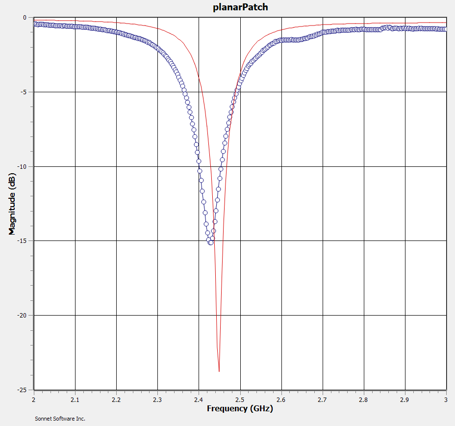
This project is still deeply in progress, but I have one working antenna so far. It is within a few MHz of the specified frequency and performs about as well as can be expected for the first revision of an antenna.
Maybe distributed element filters next…