Communications Demonstration Board (2022, Age 16)
I’m sure you know the feeling. You’re scrolling Hackaday, and you see a post so cool that it hits you- and you think “How did I NOT think of that?”
Yeah. This is one of those.
I was scrolling and I found an underappreciated post, with a proof-of-concept Twitter thread attached. I was hooked. An hour from first opening the article, I had it on a breadboard with a 2N7000 and some LEDs.
This Twitter thread- to my understanding- was nothing more than a cool concept. As in the great engineering way of reinventing the wheel, I wanted to take this and run with it. And I did. A first draft PCB was made, which streamlined the form factor, cleaned up the layout, and swapped the MOSFET for a far more suitable option.
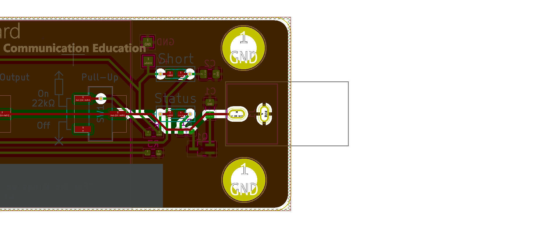
A buzzer spot for “short” detection, relying on the principle that a “short” that may drain the battery would result in a current draw that could be measured. In my infinite and neverending wisdom, I specified and purchased a buzzer that needed a square wave applied. I also realized that, especially in a classroom environment, a shrill buzzer is decidedly not the warning method of choice for such a minor issue as a minorly decreased battery life. This was replaced in the second and final revision with a much tamer LED, that will illuminate when the high output of the board is connected to the low output of another.
All of the circuitry that the user does not need to see is laid onto the back side of the board, as to simplify the experience for the end user. Vias were avoided to give a clean appearance to the front side of the board, with helpfully labeled LEDs and switches.
To complement these, I made a short video series with some pretty solid explanations of digital communications. Check it out! (Source code and hardware designs)