RF Board 2 (2022, Age 16)
I did it again.
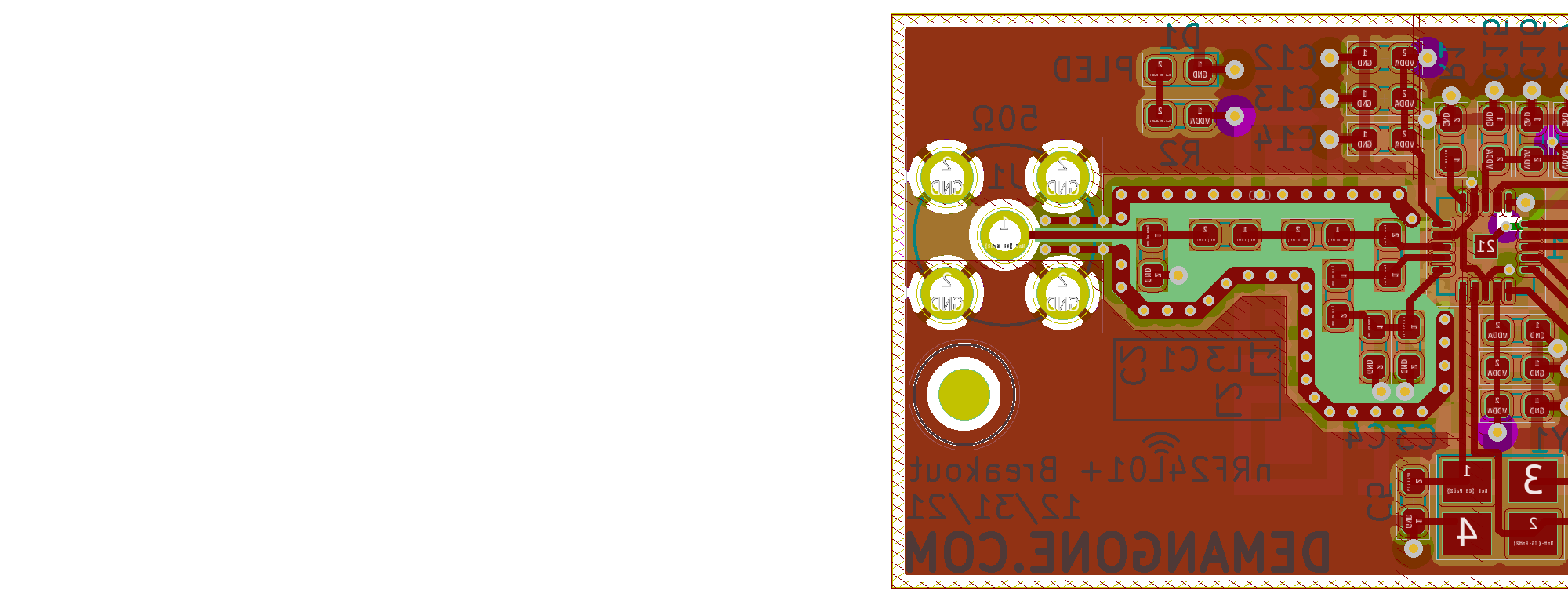
The task sounded somehow even simpler this time around; design, spin, assemble, and never touch again a breakout for the remaining nRF24L01s I have in stock from RF Board 1. This time, I nixed the antenna, and the integrated balun, and stuck closer to the manufacturer's recommendations. Simple, right? I wish.
Jumping into this, my first design decision was that I was going to use an SMA connector rather than an onboard PCB antenna, and replace the integrated balun with ridiculously small pads with 0603 passives.
I had the PCB made with JLCPCB, with the parts partially spare from last time, and a few additions from DigiKey. Unsurprisingly, the second revision also did not work. It is likely that a good ground connection was not made between one of the pins of the nRF24 and the PCB. This is a soldering issue, and I have verified that the digital side of the chip is functional. This is a (half) working design!
Third time’s a charm?