
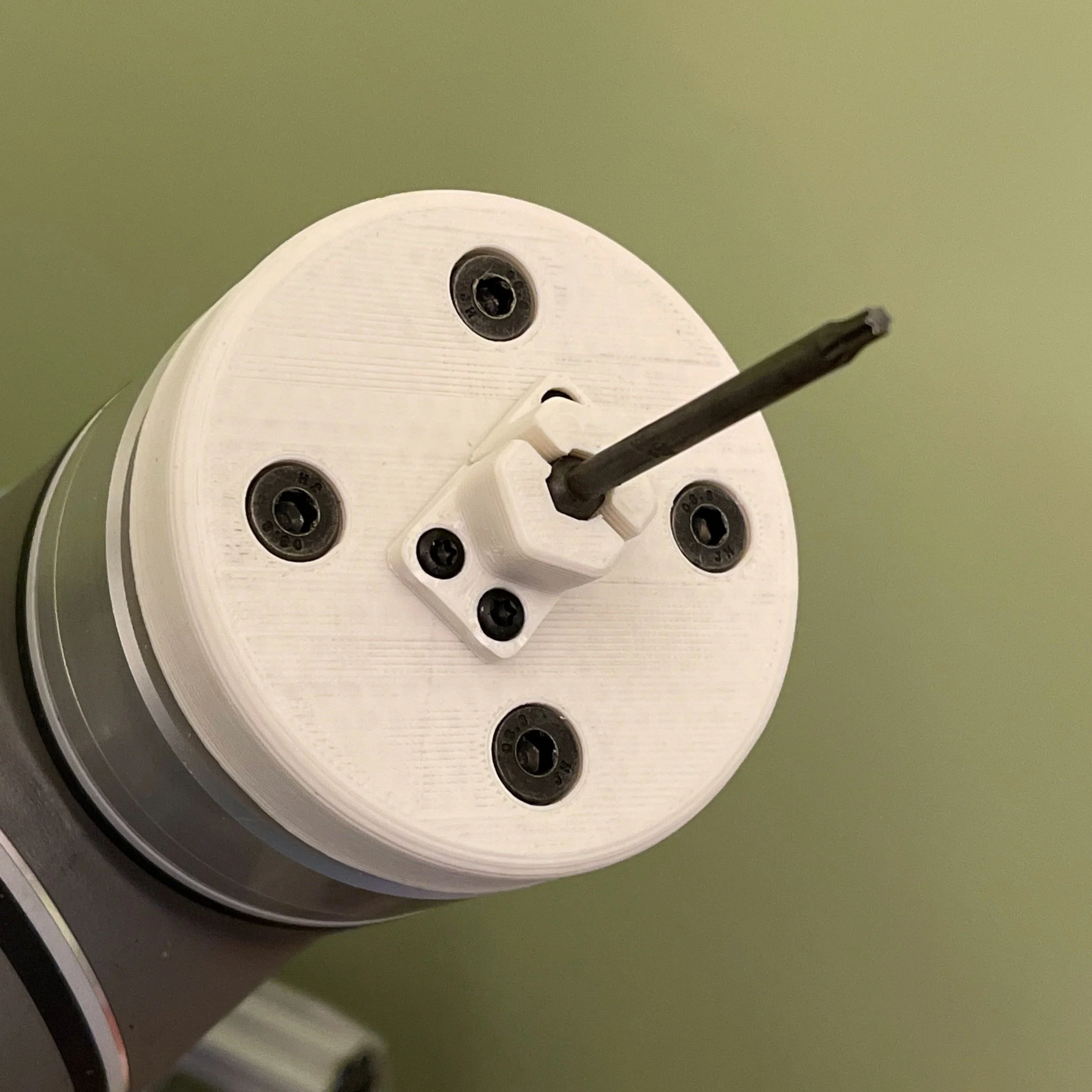
Custom-designed end-of-arm tooling with Torx driver (without webcam).
Wrangling robots, part 2 (2021, Age 16)
When life gives you a Universal Robots UR5 Cobot, make cool programs!
I had the opportunity to have a UR5 and vision system on loan to me for a few months, but it came with a challenge attached: Teach the robot to pick up screws from a COTS screw feeder designed for humans and have it drive them. For 10,000 uninterrupted cycles.
This sounded a lot simpler to me than it actually was.
My approach was straightforward: design some custom end-of-arm tooling to hold a Torx driver, pick up the screw from the screw feeder, check that it is on the end with a Keyence vision system, and “place” it. I opted to drop the screw back into the screw hopper instead of driving it to reduce complexity for the first phase.
This sounded a lot simpler to me than it actually was.
As it turns out, the hard part is not telling the robot how to do it, or even getting it to hit the same mark on repeat. It is getting the screw feeder to STOP MISFEEDING. For whatever reason, the screw feeder would love nothing more than to ruin my day by trying to present a screw that was entirely sideways, or even just refusing to present a screw at all! These machines cost thousands per unit!
I further honed my program to be more reliable, even in the face of a less-than-reliable world outside of it. By sliding the head of the driver across a metal shield near the opening of the screw feeder while applying a small amount of force, I could increase the feed reliability by restricting the cavity through which screws could feed.
I also had the driver rotate 45° so that it was likely that the edges of the Torx head on the driver would slot into place on the screw head, thus eliminating a robot-side failure mode. Furthermore, the machine was also modified to make it so that the shield would lead the screwdriver directly to where the screw head would be, along with changing the position of sensors to make it more strict.
A vision system from Keyence was employed to ensure that a screw was mounted onto the driver. Due to the usage of magnets on the driver, a common failure mode during a misfeed would be a screw becoming attached to the shaft, but not seated onto the driver coaxially, or worse yet, no screw at all. It would take a picture of the end of the driver (the flash of light in the video), and determine whether the object on the end of the driver was sufficiently coaxial, before sending a pass/fail signal to the I/O of the robot.
Despite all of this, it would not make it even close to the goal before a cycle failed, usually by fault of a particularly tricky misfeed. A new solution was devised; attaching my own camera to the end of arm tooling, and using machine vision with OpenCV to determine the location of the head of the screw, and feed the coordinates to the robot in order to correct for many misfeeds involving an offset screw head.
A consumer webcam was sacrificed to technological progress, and the bare webcam PCB was mounted on the tool. At first, the video feed was too dark, but the addition of two white LEDs to the area near the camera sensor solved this. Well-lit images were now being fed to a computer, and could then be processed by OpenCV to determine firstly where the socket was in the image, and then compute from there the position offsets that the robot must perform to reach the screw. Although these computations were performant and produced sensible guidance in testing, at this point, I was running short on time. Although I had all the tools to make a closed loop correction system for the robot, ultimately the practical considerations of time put an end to this.
The end result I got was still really cool, though. Take a look!